PPG Overview
This module demonstrates photoplethysmography (PPG) sensing using the Renesas DA14531 Pro Development Kit and the Maxim Integrated MAX86141 optical sensor.
The example is designed for the KuoQuo Pivot smart ring proof-of-concept platform and provides:
- MAX86141 initialization
- LED configuration
- PPG sample acquisition
- FIFO support
- Interrupt-driven sampling
- Motion-aware biometric sensing
- Optional BLE GATT service integration
The same hardware setup supports two firmware variants:
| Firmware Variant | Description |
|---|---|
| Basic | Simple MAX86141 communication and sensor validation |
| Basic + BLE | Real-time PPG streaming over Bluetooth LE |
Prerequisites
Before starting this example, it is recommended that you have successfully completed the DA14531 Blinky Peripheral Example (Renesas Official Guide)
This ensures:
- SDK environment is properly configured
- Keil setup is working correctly
- Flashing and debugging are functional
- UART and GPIO configuration are verified
Additional Reference (PPG Sensor)
For MAX86141-based development, it is recommended to review the MAX86140EVSYS Datasheet (Analog Devices / Maxim Integrated)
This helps ensure:
- Proper understanding of optical PPG operation
- LED timing and current configuration awareness
- FIFO and interrupt behavior interpretation
- Alignment with evaluation hardware reference design
Getting Started
Requirements
Hardware
Info
This tutorial explicitly utilizes the DA14531 Pro Development Kit. However, you can also use the DA14531 USB Development Kit—just be sure to adjust your pin configurations and jumper settings accordingly.
- DA14531 development board
- MAX86141OSBEK
- 0.3 mm pitch to 2.54 mm 25-pin FPC (flexible flat cable) adapter board
- Jumper wires
Software
- Keil uVision
- DA14531 SDK6
- J-Link or UART flashing tool
Hardware Preparation
The MAX86141 (Slave) is connected to the DA14531 Pro Development Kit (Master) using SPI mode.
Wiring Diagram
Note
- J1 and J2 are general-purpose breakout headers from the DA14531 Pro Development Kit.
- GPIO references in this guide correspond to pins exposed through these headers.
- Wire colors are recommendations only and can be changed as needed.
- SPI mode is used for this example.
- INT is optional but recommended for interrupt/FIFO-based applications.
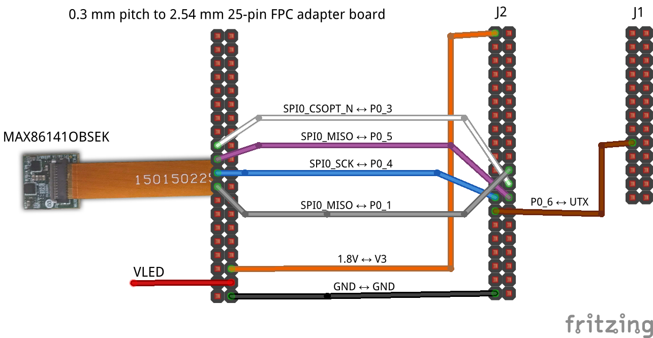
Pin Connections
| MAX86141 Pin | DA14531 Pin | Function | Wire Color |
|---|---|---|---|
| 1.8V | V3 | Power (1.8v) | Orange |
| VLED | - | Power (3.3v - 5v) | Red |
| GND | GND | Ground | Black |
| SPI0_SCK | GPIO0_4 (SPI_CLK) | SPI Clock | Blue |
| SPI0_MOSI | GPIO0_5 (SPI_DI) | SPI MOSI | Grey |
| SPI0_MISO | GPIO0_1 (SPI_DO) | SPI MISO | Purple |
| SPI0_CSOPT_N | GPIO0_3 (SPI_CS) | Chip Select | White |
| - | GPIO0_6 | UART TX Debug | Brown |
PPG Basic
Simple hardware validation and MAX86141 communication testing.
Features
- SPI communication
- Device ID verification
- LED configuration
- FIFO sample reading
- Raw PPG data acquisition
- UART debug logs
Intended Use
- Sensor bring-up
- Hardware debugging
- Driver development
- Optical signal validation
PPG Basic + BLE
This section is currently under development.
We’re actively working on it and will have updates available soon. Thank you for your patience!