Create Your Dev Board
Build your own KuoQuo Pivot Development Board and prepare it for firmware development, debugging, hardware validation, and rapid prototyping.
🚀 Quick Start Video
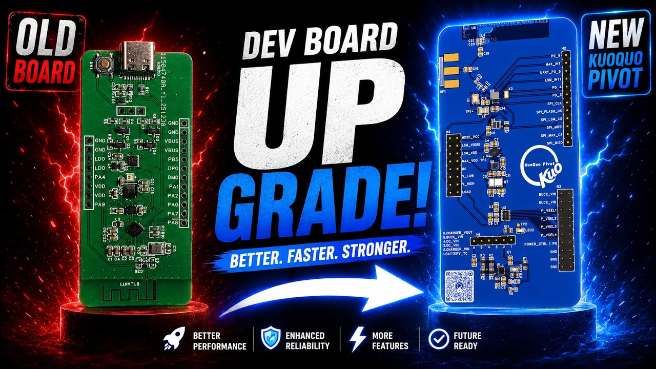
KuoQuo Pivot Dev Board Assembly Video
What You'll Build
The KuoQuo Pivot Dev Board provides:
- 📡 BLE development and testing platform
- 🔍 SWD debugging access
- 🎤 Sensor development support
- ⚡ Rapid firmware iteration
- 🛠️ Hardware validation platform
Required Components
:::info Verify that all components are available before starting assembly. :::
Bill of Materials (BOM)
| Qty | Designator | Value / Part | Manufacturer Part Number | Manufacturer |
|---|---|---|---|---|
| 5 | C3, C6, C11, C12, C14 | 10µF | CL10A106KP8NNNC | Samsung |
| 4 | C4, C7, C9, C13 | 100nF | CL10B104KB8NNNC | Samsung |
| 3 | C8, C10, C15 | 1µF | CL10A105KB8NNNC | Samsung |
| 2 | C17, C18 | 1.8pF | GJM1555C1H1R8WB01D | Murata |
| 1 | C19 | 10pF | CL10C100JB8NNNC | Samsung |
| 1 | C20 | 1pF | GJM1555C1H1R0BB01D | Murata |
| 1 | C21 | 2.7pF | GJM1555C1H2R7WB01D | Murata |
| 1 | L1 | 2.2µH | XRTC160865S2R2MBCA | XR |
| 1 | L2 | 2.2µH | DFE201612E-2R2M=P2 | Murata |
| 1 | L3 | 3.3nH | LQG15HS3N3B02D | Murata |
| 1 | L4 | 5.6nH | LQG15HS5N6S02D | Murata |
| 1 | LED2 | Red LED | XL-1608SURC-06 | XINGLIGHT |
| 1 | R11 | 270Ω | FRC0603F2700TS | FOJAN |
| 1 | RF1 | SMA Connector (18GHz) | 732511153 | Molex |
| 1 | U1 | Power Management IC | BD71631QWZ-TR | ROHM |
| 1 | U2 | 6-Axis IMU | LSM6DSOXTR | STMicroelectronics |
| 1 | U3 | Buck Converter | TPS62740DSSR | Texas Instruments |
| 1 | U4 | 2Mbit Flash Memory | MX25R2035FZUIL0TR | Macronix |
| 1 | U5 | Optical PPG Sensor | MAX86141ENP+T | Analog Devices / Maxim |
| 1 | U6 | PCB Antenna (IFA) | Integrated PCB Antenna | — |
| 1 | U7 | Optical Sensor | SFH 7050A | OSRAM |
| 1 | U8 | BLE SoC | DA14531-00000FX2 | Renesas |
| 1 | X1 | 32MHz Crystal | NX2016SA-32MHZ-EXS00A-CS06654 | NDK |
| 1 | X2 | 32.768kHz Crystal | SC20S-7PF20PPM | Seiko |
Connectors
| Qty | Designator | Description |
|---|---|---|
| 1 | H1 | 1×6 2.54mm Male Header |
| 1 | H2 | 1×12 2.54mm Male Header |
| 1 | H3 | 2×10 2.54mm Male Header |
| 1 | H4 | 2×8 2.54mm Male Header |
Note
- All NP (Not Populated) components have been omitted.
- U6 is implemented as a PCB Integrated Inverted-F Antenna (IFA).
- The BOM is intended for the KuoQuo Pivot Dev Board revision shown in the assembly guide.
Assembly Steps
1. Inspect the PCB
Before soldering:
- Check for manufacturing defects
- Verify PCB revision
- Ensure all pads are clean
- Confirm no visible shorts
Tip
Starting with a visual inspection can save significant debugging time later.
2. Solder Components
Recommended approach:
- Begin with the smallest components
- Work from the center outward
- Inspect each section after soldering
Carefully align each IC before soldering:
- Verify orientation mark
- Check pin alignment
- Apply flux if needed
- Inspect for solder bridges
Warning
Double-check IC orientation before applying heat. Reversing a component can permanently damage it.
3. Install Connectors
Solder:
- USB connector
- SWD header
- Expansion headers
- Battery connector
After installation:
- Check mechanical stability
- Verify continuity
- Inspect solder joints
4. Mount Optional Modules
Depending on your configuration:
- IMU
- Microphone
- Environmental sensors
- Additional peripherals
5. Perform Initial Power Test
Before connecting a battery or programmer:
- Check for shorts between VCC and GND.
- Verify USB power rail continuity.
- Confirm expected resistance measurements.
Danger
Do not connect a power supply if a power rail short is detected.
First Power-Up
USB Power
Connect the board through USB and verify:
- Power LED turns on
- No excessive heat
- Expected voltage rails are present
Voltage Verification
| Rail | Expected Voltage |
|---|---|
| 1V8 | ~1.8V |
| VBUS | ~5V / 3.3V |
| Battery Rail | Battery Dependent |
Programming the Board
Connect Debugger
Attach your SWD debugger:
Flash Firmware
- Open your preferred IDE.
- Build the project.
- Connect the debugger.
- Flash the firmware.
- Monitor serial output.
Validation Checklist
- No visible solder bridges
- Power rails verified
- USB connection detected
- Debugger connected successfully
- Firmware flashed successfully
- Serial output verified
- Sensors responding correctly
Troubleshooting
Board Does Not Power On
Check:
- USB cable
- USB connector solder joints
- Voltage regulator
- Power rail shorts
Debugger Cannot Connect
Verify:
- SWD wiring / 1 wire UART wiring
- Target voltage
- Firmware configuration
- Debugger drivers
Next Steps
-
Flash Firmware
Learn how to build and upload firmware to your board.
-
Debug Applications
Connect a debugger and inspect firmware execution.
-
Explore Hardware
Learn about sensors, interfaces, and expansion options.
-
Start Developing
Build your first KuoQuo Pivot application.